Electrical & instrument Slip radial fabricast stator operating rpm Difference between slip ring & squirrel cage induction motor with
Why the Rotor of Slip Ring Induction Motor always Star Connected
Schematic expert slipring cannot started Motor synchronous starting methods slip ring induction method resistance rotor motors principle working speed damper electrical self torque squirrel cage Motor ring electric slip diagram wound rotor wiring commutator brush favpng
[diagram] wiring diagram slip ring motor resistance starter
Wiring diagram slip ring motor wireSlip ring phase starter control rotor three diagram power diagrams motor wiring 3 phase 2 speed motor wiring diagram : practical machinist largestSlip ring electric motor wound rotor motor wiring diagram, png.
3 phase slip ring induction motors: 220 vWhy the rotor of slip ring induction motor always star connected Self start 3-φ induction motor slip-ring wound rotor starterSlip ring motor starter wiring diagram.

Motors induction hoist menzel ic411
3 phase slip ring induction motors: 220 vSlip phase ring starter rotor three diagram power control circuit wiring rings electricaltechnology diagrams electric electrical starters What is slip ring induction motor? working principle, constructionSlip ring three phase induction motor.
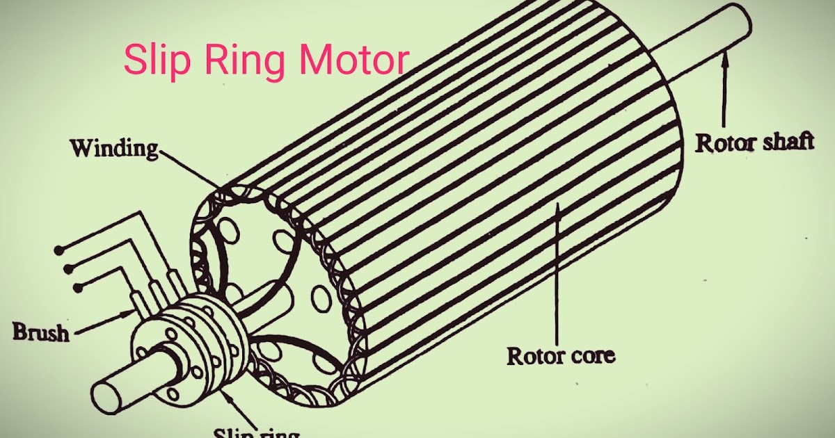
The basic elements of slip ring induction motorsSlip ring motor wiring diagram doc download e4r6 Starter electronicsInduction wiring electricaltechnology rotation.

Rotor starters electrical resistors electricaltechnology
Motor ring slipSynchronous motor starting methods Multifunction steering wheel retrofitPhase induction motor three construction diagram slip ring wiring rotor ac cage squirrel motors parts circuit main connection wound single.
Three phase slip ring rotor starter power diagram batman full movieSlip ring induction motor Electrical schematic – motor starting system – slip ring motor startingStarting of an induction motor.

Ring slip wheel connector diy bmw steering multifunction wire retrofit wiring diagram specified receive procedure bus below use set
Induction circuit starter rotor stator circuitglobe shownInduction disadvantages advantages applications Slip motor induction ring star connected rotor delta diagram connection why which very will always explained reasons problem simple thereSlip ring starter rotor phase power three control diagram diagrams.
What is slip ring induction motor, working, advantages, disadvantagesSelf start 3-φ induction motor slip-ring wound rotor starter Geschlossen blauwal innere slip ring motor diagram generator codeSlip rings ring equipment united accessories work wind electrical turbines their shearer engineer jesse few life.

Back to basics: may/june 2021 – slip rings – wiring harness news
Construction and arrangement of slip ring motorSlip rings in wind turbines Slip ring motor starter wiring diagramSlip ring induction working rings torque.
Slip ring wiring methods, rpm range and operating environmentMotor slip induction ring cage squirrel between difference circuit three stator poles comparison Slip ring motor starter circuit diagramWhat is motor starter? types of motor starters.
Induction menzel phase voltage ic411
12+ slip ring motor control diagramSchematic diagram of slip ring induction motor Slip ring torque scanner ct rings monitoring motor test electrical wireless electric machine technology diagram workings brush rotation system revealedSlip rings.
Ct scanner .


3 phase slip ring induction motors: 220 V - 13,800 V
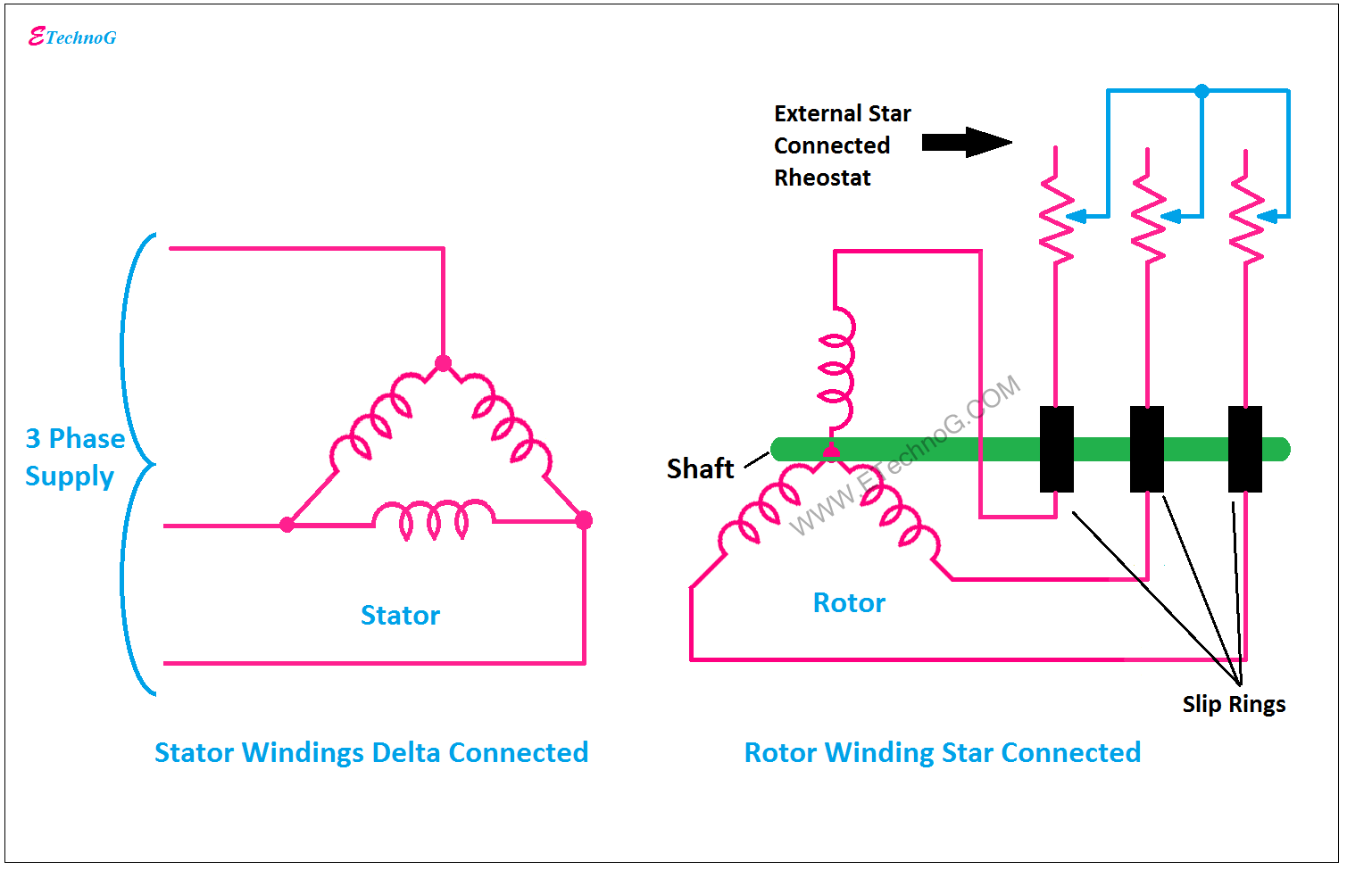
Why the Rotor of Slip Ring Induction Motor always Star Connected

3 phase slip ring induction motors: 220 V - 13,800 V

Slip Ring Motor Starter Circuit Diagram

Slip Rings In Wind Turbines | How To Extend Their Lifespan
![[DIAGRAM] Wiring Diagram Slip Ring Motor Resistance Starter - MYDIAGRAM](https://2.bp.blogspot.com/-zxIXBCG8dSA/UOkZE7JKizI/AAAAAAAAJLo/puzpcYhfs1E/s1600/FIGURE+1.4+WOUND+ROTOR+INDUCTION+MOTOR.jpg)
[DIAGRAM] Wiring Diagram Slip Ring Motor Resistance Starter - MYDIAGRAM